
- Program download at the BIMserver.center platform
- New program
- Code implementation and improvements in its application
- CYPECAD
- CYPELEC Networks
- CYPEPLUMBING Sanitary Systems
- CYPESOUND
- AcoubatBIM by CYPE
- CYPETHERM HE Plus, CYPETHERM RECS Plus and CYPETHERM EPlus
- Arquimedes
- Return to the 2018 version download area
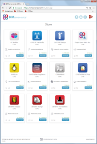
Program download at the BIMserver.center platform
The following programs: CYPELEC Networks, CYPEFIRE Design, StruBIM Analysis, StruBIM Design, and StruBIM Foundations are available to be downloaded at the BIMserver.center platform.
New program
CYPEFIRE Design (MEP group)
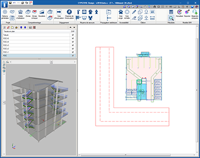
CYPEFIRE Design is a program that has been created to help project designers during the design and verification process of the properties of the building and fire safety installations.
CYPEFIRE Design can be downloaded at the BIMserver.center platform.
In its first version, CYPEFIRE Design allows users to design and analyse fire safety installations in accordance with the Moroccan code: “Règlement de sécurité contre les risques d’incendie et de panique dans les constructions”, for which the code limits can be edited.
More codes from other countries will be added in upcoming versions (also with the option to edit the code limits). Users will have the possibility to define personalised design configurations to verify codes that have not been included previously in the program.
The graphical interface allows users to quickly create and edit the main properties of a fire safety project (Sector compartmentation, limit outdoor propagation, evacuation means for occupants, protection installation, access for firemen, etc.)
CYPEFIRE Design is integrated in the Open BIM workflow using the IFC standard.
More information in CYPEFIRE Design webpage.
Code implementation and improvements in its application
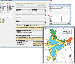
Loads on structures. Earthquake loads
IS 1893 (Part 1): 2016 (India)
CRITERIA FOR EARTHQUAKE RESISTANT DESIGN OF STRUCTURES.
Part 1. General Provisions and Buildings.
Implemented in CYPECAD and CYPE 3D.
NSR-10 (Colombia)
Decree 945 of 5 June 2017 published by the Ministry of Housing, City and Territory of the Republic of Columbia partially modifies the “Reglamento Colombiano de Construcción Sismo Resistente NSR-10”.
In the 2018.c version of CYPE programs, the changes indicated in this decree, which affect CYPECAD and CYPE 3D, have been implemented. These changes allow users to select certain municipalities that were previously omitted in the NSR-10 Regulation.
The municipalities that have been added are: Norosí (Bolívar), Guachené (Cauca), San José de Uré (Córdoba), Tuchín (Córdoba), Nariño (Nariño) and Coveñas (Sucre).
CYPECAD
Snap to post-tensioned tendon ends
New snap points have been implemented in the introduction of post-tensioned tendon ends. In previous versions, when a tendon was introduced that crossed one or more panels, it was only possible to snap to the edges of the external beams. With this improvement, intersections with internal beams of the floor slab can be snapped to.
Link project to BIM model
As of the 2018.c version, it is possible to import a BIM model in a CYPECAD project that has already been started, and in which no new floors have been defined. This improvement allows for links to be created with empty projects where the options in ‘General data’ have been previously configured.
The ‘Import’ button will appear as active in the ‘Beam Definition’ tab when no floors have been created in the project.
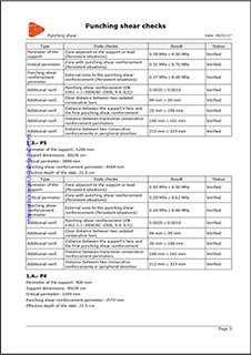
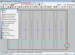
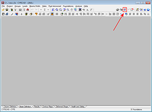
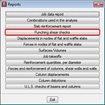
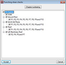
Punching shear check report
The report ‘Punching shear checks’ has been implemented. This report shows a summary of the punching shear checks that have been carried out for the selected columns.
Snap to polygons in generic column sections
New tools have been implemented in the editor for columns with generic sections. One tool snaps to sections and the other snaps to openings of DXF or DWG templates. Both snap to closed polygons.
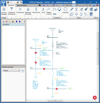
CYPELEC Networks
Available at BIMserver.center
CYPELEC Networks is now available to be downloaded at the BIMserver.center platform.
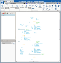
Status loadcase
To manage the operation status of the installation elements, the 2018.c version includes the definition of the status loadcase. These loadcases define the status conditions of:
- Simple contacts and commutation contacts
- Fuses and switches
- Operation regimes in motors
- Operation regimes in generators
From the start, the circuit diagram is assigned to one loadcase (which can be unique) and is referenced on the left of the user interface.
Using the icon next to the reference of the visible loadcase, the loadcases can be generated in a panel created for this purpose and in which the status of all the previously mentioned elements are listed. Furthermore, the status can be changed directly in this panel.
The panel allows users to select the loadcase which is to be listed, as well as an option to only view the status differences of the elements of the selected loadcases.
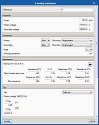
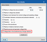
Voltage limits in the selection of the transformer tap changer
From the first version of CYPELEC Networks, when a two winding transformer and a three winding transformer are edited, users can configure and the select the tap changer with the aim to regulate the voltage in the buses connected by the transformer.
After the analysis process, it may occur that the selection of the tap changer may cause the voltage of the controlled bus to lie outside the maximum values specified in the panel. As of the 2018.c version, when this case arises, the program can emit a warning to tell users to carry out a check. This warning is emitted if the new check “Voltage limits in the selection of the transformer tap changer” is activated, which is done in “General settings” > “Line checks”.
CYPEPLUMBING Sanitary Systems
NTC 1500. Columbian plumbing code
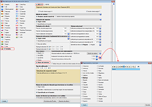
The Columbian Plumbing Code, NTC 1500, has been added to the collection of design codes of CYPEPLUMBING Sanitary Systems has available to analyse and design wastewater and rainwater evacuation installations.
Therefore, as of the 2018.c version, users can apply a personalised design configuration, which allows for personally configured design values to be used or apply the standard configuration in accordance with the following design codes:
- CTE DB HS5 (Spain)
- NBR 8160:1999 and NBR 10844:1989 (Brazil)
- NTC 1500 (Colombia)
- RGSPPDADAR (Portugal)
- EN 12056 (European Norm)
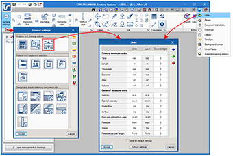
Units of measurement
As of the 2018.c version, when a country is chosen to select the code that is going to be applied for the design and check of the wastewater and rainwater installation, the program automatically selects the units of measurement used in that code.
In the “General settings” dialogue box, a new button has been implemented that opens the “Units” panel, from which users can edit the units of measurements and the number of decimal places of the magnitudes that are used in the program.
The “Units” dialogue is the same as that which has appeared as of previous versions with the “Units” option of the drop-down menu that appears when the globe icon in top right-hand corner of the screen is selected. Now, this unit edit dialogue is more accessible from the “General settings” menu.
CYPESOUND
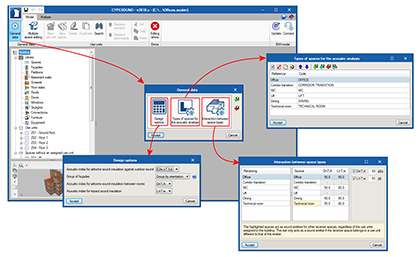
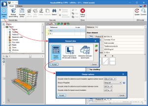
General options
All the information regarding design options and acoustic index limits that are used have been grouped in the “General parameters” panel.
Thanks to this implementation, it is now possible to create diverse acoustic requirements, for example, based on different national codes, and save this information with the aim to use it later in other projects.
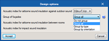
Façade groups
The option “Group of façades” has been added to the “Design options” panel of CYPESOUND.
Using this option, users can configure the way in which the outdoor airborne noise insulation is to be verified. As well as the individual analysis of each façade that has been carried out up to now, it is now possible to combine all the façades and check the insulation of the complete envelope of each space. The program also allows for adjacent façades with the same orientation to be grouped and then determines the insulation of these combined elements. Finally, the possibility also exists to group façades depending on their type (façade, roof or overhang), and calculate each group of insulation.
AcoubatBIM by CYPE
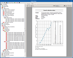
Report views
The views of the documents generated by the program have changed so the sound tests of the products of the database and analysis results can be seen. Now a report view that can be configured is generated and can be adjusted to the program window.
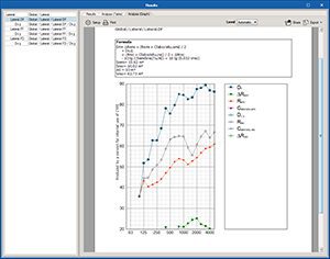
Deviation of the calculated noise index
In the results table of each space, a new column has been added that represents the deviation between the value obtained for each sound index and the limit that has been established for the project. This way, users can identify which are the weakest elements, as well as if any oversized elements have been placed.
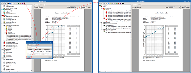
Advanced search in the database
A new advanced search button has been introduced for sound tests. This option allows users to filter elements depending on certain parameters such as mass or thickness. Users can indicate a text chain as the product reference and a minimum or maximum value, or range for each active variable.
General options
All information regarding design options and applied sound index limits have been grouped in a general data panel for the project. This panel can be accessed via the “General data” button of the toolbar.
Thanks to this implementation, it is now possible to create multiple sound requirements; such as those related to different national codes, and save this information to be able to use it later in other projects
CYPETHERM HE Plus, CYPETHERM RECS Plus and CYPETHERM EPlus
Aerothermal equipment. TOSHIBA Estia system
Aerothermal equipment consists of a heat pump that produces hot water for heating and sanitary hot water, with the possibility to invert the cycle for cold production. In the 2018.c version, CYPETHERM programs with the EnergyPlusTM analysis engine (CYPETHERM HE Plus, CYPETHERM RECS Plus and CYPETHERM EPlus) are capable of simulating this air conditioning system based on its behaviour curves, and incorporate TOSHIBA’s Estia system.
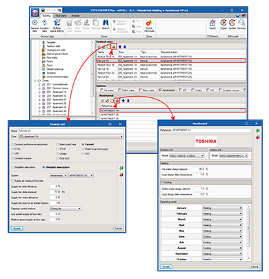
Introduction of TOSHIBA Estia systems
When users select the “Air conditioning systems” section, located in the tree diagram of the “Building” tab (to the left of the screen), the Aerothermal tab appears in the “Systems” section (middle of the screen). Here, users can add and define this type of systems to be added in the project. Users can choose, in the panel, amongst the different outdoor and indoor TOSHIBA Estia system units, and choose whether the system will only be used for heating or also for cooling. Users must specify the working temperature conditions of the installation and its operation mode during the year.
Aerothermal systems can be connected to “Low-temperature radiant heating terminals” (only heating), also implemented in this version; and to fan coil terminals (heating and cooling). In the panel of these last items, users must specify whether the fan coil is to be connected to a conventional water distribution, as up to now, or to an aerothermal system. Within the same thermal zone, it is possible to define any number of terminal units associated to aerothermal systems. In the simulation, EnergyPlusTM will sequentially use the terminal units that are located in the same zone, in the order defined in the Terminal units lists.
The aerothermal system can be used to produce sanitary hot water. To do so, users must define it in the “DHW systems” section, located in the tree diagram of the “Building” tab. If users wish to use the same aerothermal system for air conditioning and hot water, the same outdoor unit model must be selected in both windows.
Open BIM workflow. Import TOSHIBA Estia aerothermal equipment from IFC files
TOSHIBA Estia aerothermal equipment defined in CYPETHERM HVAC can be imported directly in CYPETHERM programs with the EnergyPlusTM analysis engine (CYPETHERM HE Plus, CYPETHERM RECS Plus and CYPETHERM EPlus) via the Open BIM connection using the IFC standard.
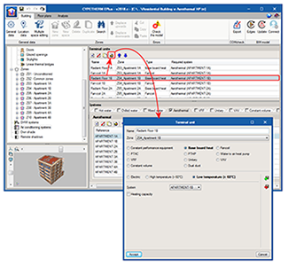
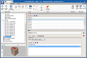
Low-temperature radiant heating terminal
When the “Air conditioning systems” section is selected (tree diagram of the “Building” tab), in the “Terminal units” window that appears, the “radiant heating terminal” has been divided into different groups: Electric, High temperature (> 60ºC) and Low temperature (< 60ºC).
Until now, for these terminals, users could choose between “Electric” and “Hot water”. As of the 2018.c version, “Hot water” has been divided into “High temperature (> 60ºC)” and “Low temperature (< 60ºC)”.
The new “Low temperature (< 60ºC) type is more adequate to simulate systems such as radiant floors or radiators that operate with water at less than 60ºC. In the 2018.c version, the low temperature radiant heating terminal is only compatible with the Aerothermal system (also implemented with this version).
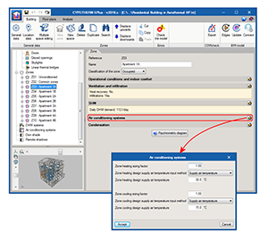
Design conditions of air conditioning systems
A new section has been added in the Zone window (which appears when a Zone is selected in the tree diagram of the “Building” tab): Air conditioning systems. This section gathers, in a single panel, all the design conditions of air conditioning systems that were previously defined in panel of each terminal unit.
In the new panel, users can specify the design temperature (or temperature difference) of the discharge air of the zone, for both heating and cooling. A scale factor is also defined for each mode (heating or cooling), which will be applied to the design flows and loads of the zone calculated by EnergyPlusTM.
Arquimedes
Bill of quantities of Revit models
Job item assignment by key notes
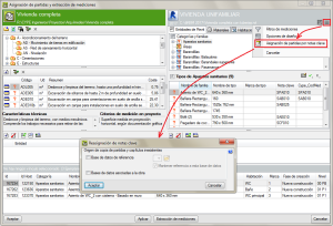
If Key notes are defined in the Revit model, with job item codes (in order to assign a type of the Revit model to the job item), the program will ask for the copy origin of inexistent job items and chapters, the first time the Revit model is linked to an Arquimedes project. This way, once the Revit model has been imported, the Types that contain a Key note that can be located in the Arquimedes project (or in the referenced database or database associated to Arquimedes) will be assigned to the job item that is indicated in the Key note.
The button Job item assignment by key notes  allows users to assign a Type of the Revit model that has been defined in a Key note to a job item, if linking process has already been carried out between the Revit model and the Arquimedes project.
Report templates
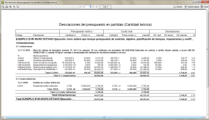
Budget deviation in job items (theoretical quantity)
A new report template has been implemented: “Budget deviation in job items (theoretical quantity)” (pl_cb007c.pla), located in the “Job control” category. In this template, the theoretical quantity can be compared to the executed quantity and the reference price to the average execution price in unit items. This way, the price deviation, between the reference price in the job control and the execution price can be seen.
Return to the 2018 version download area
Tel. USA (+1) 202 569 8902 // UK (+44) 20 3608 1448 // Spain (+34) 965 922 550 - Fax (+34) 965 124 950