
- New modules and programs
- IFC Builder
- CYPECAD
- Generic material columns
- Concrete columns with generic sections
- Join the longitudinal reinforcement of a column start to the reinforcement of the first span
- Column force visualisation improvements
- Reading of walls and partitions of the BIM model
- Deflection limits of joists depending on their material
- Take-off report
- Project comments
- CYPE 3D
- CYPE-Connect
- AcoubatBIM by CYPE
- Edit the ProductID in the personalised elements of the database
- Reference of acoustic measurements
- Description of the database products
- Links to manufacturer websites
- Comparison of database products
- Calculation of airborne noise transmitted by air inlets
- Calculation of airborne noise transmitted by roller shutter boxes
- List of products used in the project
- Improvement in the aspect of results
- Adjustment of graph scales
- Grouping of façades
- CYPEFIRE Sprinklers
- CYPETHERM HE Plus, CYPETHERM RECS and CYPETHERM EPlus
- CYPETHERM HVAC
- Arquimedes
- Return to the 2018 version download area

New modules and programs
Structures group
Generic material and generic section supports, and reinforced concrete supports with generic sections (CYPECAD module)
The 2018.a version includes this new CYPECAD module, which has been developed to:
- Calculate the forces of generic material columns, which are defined by providing their modulus of elasticity, Poisson’s ratio and specific weight.
- Calculate the forces of generic reinforced concrete sections and check their longitudinal reinforcement.
More information on the properties of this CYPECAD module can be found in the sections on Generic material columns and Concrete columns with generic sections of this webpage.
MEP group
CYPEPLUMBING Sanitary systems
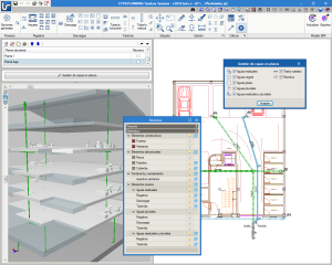
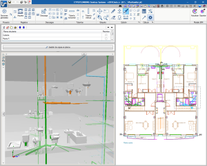
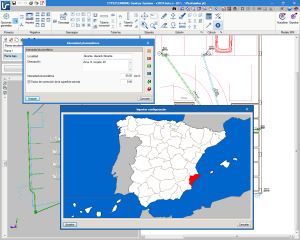
CYPEPLUMBING Sanitary Systems is a program created to help project designers with the design and analysis of foul water and rainwater evacuation systems. It is integrated in the Open BIM workflow using the IFC standard.
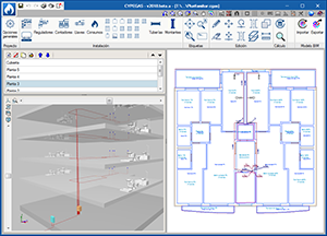
The program allows for a part or all of the installations to be designed of any type of building, and the different networks (foul, rain, mixed, grey and black water) can be organised in layers and managed in 2D or 3D. The program contains material catalogues which can be completely configured, and generates floor plans, drainpipe diagrams, result and check reports, and quantity reports that can be exported to FIEBDC-3.
CYPEPLUMBING Sanitary Systems allows users to design the installations using tables or by applying a hydraulic analysis using several formulas (Manning, Wyly-Eaton, Dawson and Hunter). An automatic design of the installation can be carried out, optimising the space required by the pipe in the free height of the floor and the evacuation volumes.
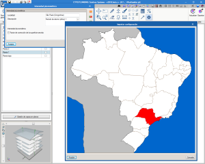
The program includes predefined code-complying configurations: CTE DB HS5 (Spain), RGSPPDADAR (Portugal), NBR 8160:1999 and NBR 10844:1989 (Brazil) EN 12056. It is also possible to configure design checks to ensure code and personal technical limits are met.
More information can be found on the CYPEPLUMBING Sanitary Systems webpage.
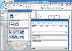
CYPEGAS
CYPEGAS is a program created to help project designers with the design and analysis of the foul water and rainwater evacuation systems. It is integrated in the Open BIM workflow using the IFC standard.
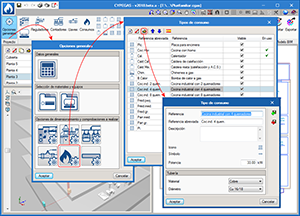
The program consists of a graphical interface which allows users to configure any type of gas consumption; introduce an installation on 2D templates from the BIM model (via IFC), or on DXF, DWG, DWF templates or images (jpeg, jpg, bmp or wmf); and view the installation in real time in 2D and 3D.
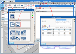
CYPEGAS contains predefined material catalogues, which can be completely configured, and allows users to introduce other material catalogues based on the existing catalogues or create them using data users have available.
CYPEGAS generates floor plans of the installation, and results, materials and quantity reports. It is also possible to export the quantities to FIEBDC-3 format.
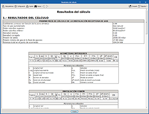
The program designs the installation using the Renouard formula and analyses the installation arrangement by calculating gross and simultaneous quantities of flow, with the possibility to configure global simultaneity.
It is possible to configure design checks to ensure code and personal technical limits are met. In this first program version, predefined configurations can be imported that meet the requirements of the UNE 60670-4 code (Spain), and is installed in Spanish or Portuguese. The program displays the check warnings of elements that do not meet the established checks.
More information on this new CYPE program will be available shortly.

CYPETHERM group
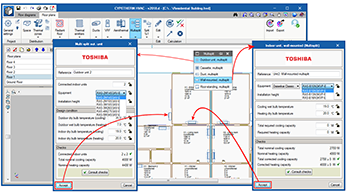
TOSHIBA multi split systems (CYPETHERM HVAC module)
The 2018.a version allows users to design TOSHIBA multi split systems with outdoor units to which 2 to 5 indoor unit can be connected.
More information on the inclusion of these air conditioning systems can be found in the TOSHIBA multi split systems section of this webpage.
New programs that can be downloaded from BIMserver.center
CYPEURBAN and CYPELEC Networks (new programs with the 2018.a version) and StruBIM programs (from previous versions) are not installed with the complete CYPE program packet. These programs must be downloaded via the BIMserver.center web platform.
Furthermore, to be able to use either application, users must register in the BIMserver.center web platform. Once the program has been downloaded and installed, as well as the “BIMserver.center” synchroniser, new projects created by users should have an associated project lodged in the platform, hence allowing for the collaborative Open BIM workflow to take place.
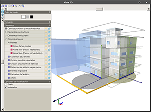
CYPEURBAN
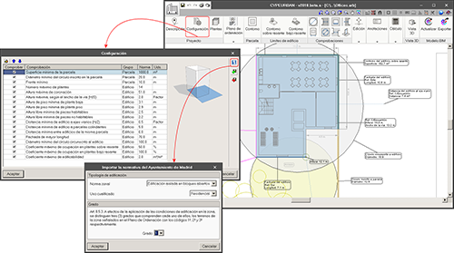
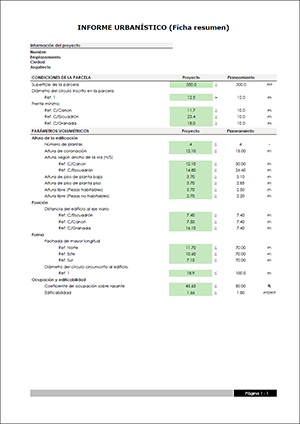
CYPEURBAN is a program that has been developed to provide the documents of the fulfilment of urban requirements of BIM models in IFC format.
This application has been developed by CYPE with the technical advice and supervision of the Association of Developers of Madrid (ASPRIMA), and is the result of a collaboration agreement with the aim to facilitate and improve the quality of the justification process and validation of urban planning regulations using BIM models.
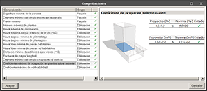
The program has a calculation logic that allows to deduce, based on a BIM model, some of the urban planning checks required by municipal ordinances. It consists of a series of tools to define and check parameters such as distances from the building to adjacent plots, plot checks, occupation, buildability, height levels, free heights, etc.
In its first phase, the program incorporates a library of checks of the number 5 zone code of the City council of Madrid (isolated building in open blocks).
The distribution of CYPEURBAN is free, it is installed in Spanish and Catalan, and can be downloaded via the "BIMserver.center" platform. This tool is integrated in the Open BIM workflow using IFC standard exchange files.
More information on this new CYPE program can be found in Spanish on the CYPEURBAN webpage.
CYPELEC Networks

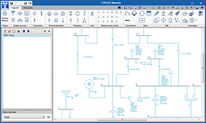
CYPELEC Networks is a program for the analysis of power systems in electrical networks, created to assist project designers in the design and analysis of high/medium and low voltage installations.
It has a simple graphical interface that allows users to easily create and edit power diagrams and circuit diagrams. It incorporates a great variety of electrical equipment to create the diagrams such as, for example, power supplies, generators, transformers (two and three windings), low and medium voltage cables, high voltage transmission lines, capacitor banks, electrical loads and motors, etc... as well as protection and other electrical devices.
CYPELEC Networks analyses the flow of charges and calculates the voltages and phase difference in bars or buses, the currents in lines and branches, and the active and reactive power flows of the electrical system.
The design checks carried out in the program are based on the specifications of the NFPA 70 National Electrical Code (NEC).
CYPELEC Networks can be downloaded via the "BIMserver.center" platform. For its first version, it may be installed in Spanish or English. This tool is integrated in the Open BIM workflow using IFC standard exchange files.
More information on this new CYPE program can be found in CYPELEC Networks webpage.
OpenSees analysis engine

As of the 2018.a version, OpenSees is incorporated as the new analysis engine for StruBIM programs: StruBIM Analysis, StruBIM Design and StruBIM Foundations. StruBIM programs are installed in English and Spanish.
OpenSees is a system of recognized prestige for the linear and non-linear analysis of structures, developed by Frank McKenna, Gregory L. Fenves and Filip C. Filippou at the University of California at Berkeley. Its use is widespread worldwide to simulate the seismic behavior of structures.
Currently, CYPE is including, in all its disciplines, highly reliable analysis engines, which are consolidated in the scientific-technical world, such as OpenSees.
To use the "OpenSees analysis engine" in StruBIM programs, the user license must include the corresponding permit that will be shortly be able to be acquired at the BIMserver.center web platform.
Download StruBIM from the BIMserver.center web platform
In previous versions, StruBIM programs (StruBIM Analysis, StruBIM Design and StruBIM Foundations) were included in the general menu of CYPE programs. As of the 2018.a version, StruBIM programs can be downloaded from the BIMserver.center web platform. This download option will shortly be available. Meanwhile, the programs can be installed individually when the complete version of CYPE programs is downloaded.
IFC Builder
Export DXF and DWG templates to the IFC model of the building
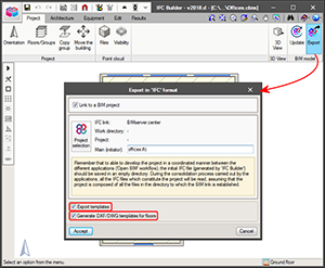
The 2018.a version of IFC Builder allows users to export the DXF or DWG templates included in the project to IFC format. IFC Builder also allows users to generate a DXF template for each floor of the project to be exported to IFC format. The program generates them based on the construction elements included in the project. These templates can be useful when no previous DXF or DWG files exist.
For all this, two options have been implemented in the Export in "IFC" format dialogue box:
- Export templates
Exports the DXF or DWG templates of the project, including what has been managed by users (layer management, displacements, angle of rotation, etc.). - Generate DXF plans per floor
The names of the DXF plans that are generated by the program are composed of the name of the project and that of the corresponding floor.
These templates can be read by CYPE programs linked to that project via the Open BIM workflow, which use a graphical data entry interface: CYPECAD, CYPELUX, CYPELEC, CYPEFIRE CTE, CYPEFIRE Sprinklers, CYPETEL, CYPEPLUMBING Sanitary Systems, CYPEGAS, CYPETHERM (HVAC, EPlus, CTE Plus, REC Plus, C.E...); and their generic and country-specific versions for those who have them.
This connection keeps the model updated with any changes that are made to the DXF or DWG templates in IFC Builder.
CYPECAD
Generic material columns
In the 2018.a version, a new type of material has been implemented for it to be assigned to columns. It is a generic material whose properties are defined by users. These columns can have a rectangular, circular, or generic section, or a section determined by the mechanical properties introduced by users. Generic material columns intervene in the force analysis of the structure. Their forces and deformed shape can be consulted, although their sections are not checked.
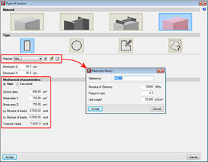
Definition of the material
Users can create a generic materials library to assign to different columns. The generic material will be defined by the modulus of elasticity, Poisson’s ratio and the specific weight.
The mechanical properties of rectangular, circular or generic columns can be established by users or calculated by the program.
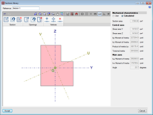
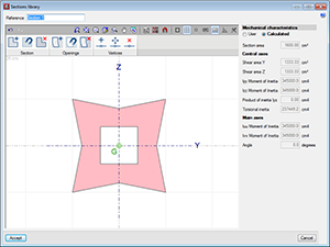
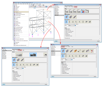
Generic sections
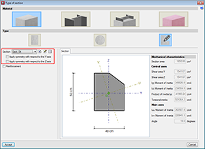
A section editor has been implemented in the program which allows users to define the geometry of the section. The sections are stored in a library which also contains generic concrete section column.
In the section editor, users can create a section by defining the points of its external perimeter and openings, if any. The outline of a previously introduced section can be edited by adding, moving or deleting vertices.
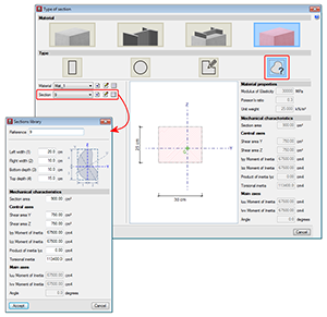
Sections defined using an equivalent rectangle
For this type of section, the dimensions are defined of the equivalent rectangle that would encompass the real section and its mechanical properties.
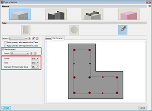
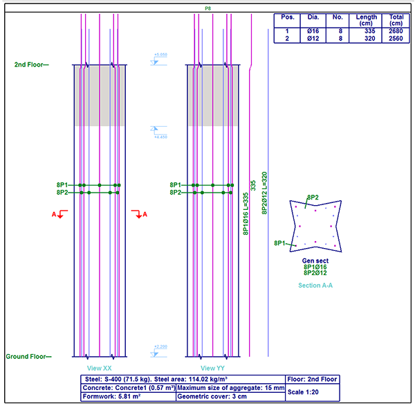
Concrete columns with generic sections
Introduction
A new type of concrete column has been implemented: generic section columns defined by users. This improvement allows users to calculate projects with columns of any shape. Until the 2018.a version, concrete columns could only have rectangular or circular sections.
Generic section concrete columns are composed of a concrete section defined by users and a longitudinal reinforcement arrangement. Both sections and reinforcement arrangements can be edited by users.
The type of concrete and type of steel will be the same as that defined for other concrete columns in "General data".
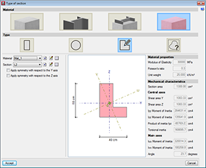
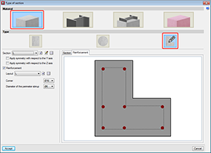
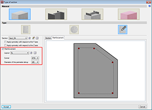
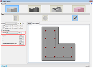
This new type of column appears in the "Type of section" panel, which is displayed when introducing or editing a column. It is possible to select a section from the library or add a new one. This section may be symmetrical with respect to the local axes. Furthermore, it is possible to define a reinforcement arrangement and the diameters of the longitudinal bars. Placing reinforcement is optional, if the 'Reinforcement' option is not activated, the column will not be checked. It will intervene in the force analysis, but no checks will be carried out on it. The reinforcement can be assigned in the "Column Definition" tab and the "Results" tab by editing the “Column schedule”.
Generic sections defined by users can be stored in a library that will be shared with generic section and material columns. Both types of columns use the same generic section editor, which has been referenced on this web page in “Generic sections” in the "Generic material columns" section.
Layout of the longitudinal reinforcement
For checks to be carried out on these columns, reinforcement must be provided. To do so, a reinforcement layout that is compatible with the section of the column and the diameters of the bars must be chosen. A reinforcement layout defined in a section will be compatible with sections of the same shape. For example, if a user defines a series of reinforcement layouts which can be used for a regular pentagonal section, these layouts will be compatible for use with another section of the same shape but with different dimensions.
The different reinforcement layouts are stored in a user-defined library.
Based on a previously introduced section, a longitudinal bar layout can be defined. Several options to define the position of the bars are included in the layout editor.
It should be noted that bars are not defined with a specific diameter, just their position. This way, a longitudinal bar layout can be used from the library for columns with bars of different diameters and even for sections of the same shape but with different dimensions.
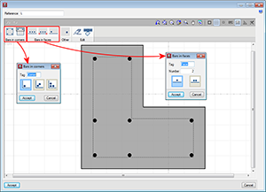
The tools of the layout editor are:
- Generate bars in corners
- Place bars in all the vertices of the section
- Introduce bars in the selected corner
- Introduce bars on one face
- Introduce bars between two points
- Introduce a bar at a free position
- Delete bar
- Define tags
Tags allow for bar groups of the same diameter to be defined, or simple to provide a reference as to their position. Each tag will be assigned a bar diameter.
Drawn in the section view is a discontinuous line, which represents the zone that lies inside the perimeter stirrup, where the corner and face bars will be placed. Therefore, the total cover of the bars defined at the corners or faces will be the sum of the geometric cover and the diameter of the perimeter stirrup.
When bars are added at corners, a panel appears where the tag can be defined, and where users can choose whether to introduce one, two or three bars. A similar panel appears with bars at the faces, where users can define the tag of these bars, the number of bars along the face and whether a single bar or two joined bars are to be placed.
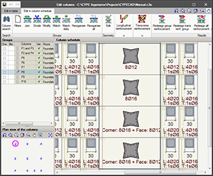
Column schedule
Users can edit and check these sections from the column schedule. The program checks the maximum and minimum reinforcement requirements and resistance against normal forces. The present version of the program does not design the reinforcement; it checks the reinforcement defined by users.
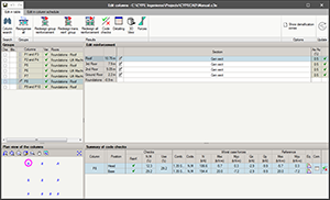
From the column schedule, users can:
- Edit the diameters of the bars of the reinforcement layouts assigned to the section.
- Add new layouts.
The same drawings and reports can be generated as for rectangular or circular columns, bearing in mind that the steel quantities do not include those of the transverse reinforcement.
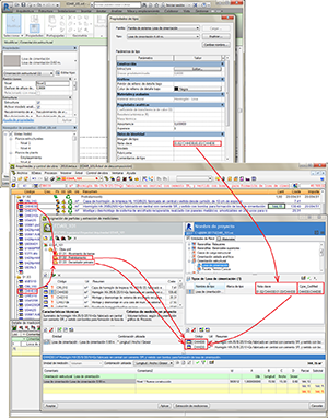
Join the longitudinal reinforcement of a column start to the reinforcement of the first span
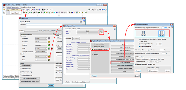
An option has been added that allows users to select whether or not to overlap reinforcement at column starts at the foundations (“Column Definition” tab or “Beam Definition” tab > Project > General data > “By position” button > “Steel types in bars” dialogue box, “Columns, shear walls, walls and corbels” button > “Reinforcement arrangement” section, “Column start options” button).
When the reinforcement overlaps are placed half-way at the floor, this option allows users to not carry out the overlap with the starts at the foundation.
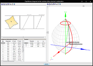
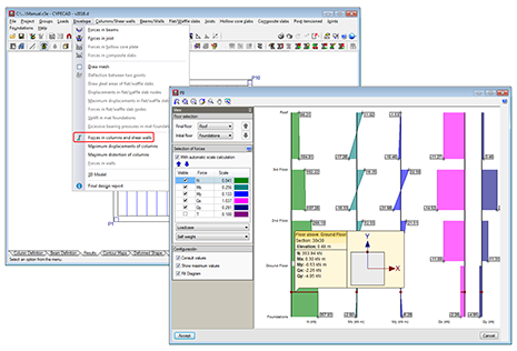
Column force visualisation improvements
The force consultation panel for columns and shear walls has been improved. From the “Envelopes” menu in the “Results” tab, users can access the new force consultation panel. It can also be accessed from the “Column schedule”.
Reading of walls and partitions of the BIM model
As of the 2018.a version, CYPECAD projects which have been started based on a BIM model can read and import walls and partitions of the BIM model as construction elements. Non-structural walls and partitions provide stiffness to the structure during an earthquake by modifying the distribution and magnitude of the forces due to the seismic action. More information on how non-structural elements interact with the structural elements against seismic action, and which properties are to be taken into account to consider their influence in the behaviour of the structure against seismic action, can be found on the Interaction of the structure with the construction elements webpage.
With this improvement, the construction elements of CYPECAD will be synchronised with the walls and partitions of the BIM model. They will be automatically introduced, if users select for them to be imported and will be updated if any changes arise in the architectonic model.
As well as providing stiffness to the structure, they will generate line loads on the floor slabs or beams on which they bear. These loads, which are laborious to introduce and modify, if any changes arise, with the 2018.a version, can be placed automatically at the position where the wall is located in the BIM model.
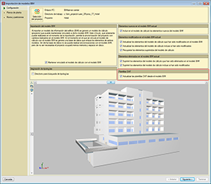
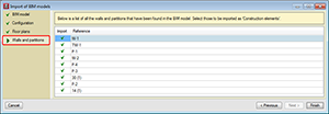
During the creation of the CYPECAD project based on a BIM model or during the update of the BIM model, a new section appears in the wizard that will list the different types of walls and partitions, so to offer users the option of whether or not they are to be imported.
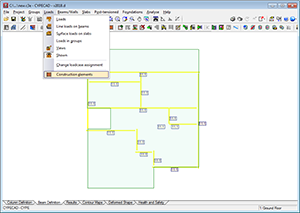
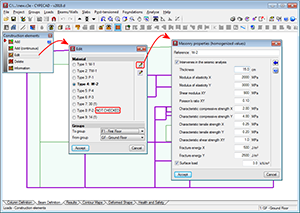
From the “Loads > Construction elements” menu, users can edit, consult and check the walls and partitions that have been imported.
Each type that is imported is defined as “NOT CHECKED”, and it is the user who will decide how the walls will affect the structure: whether they intervene in the seismic analysis and/or if loads on the floor slabs are to be generated.
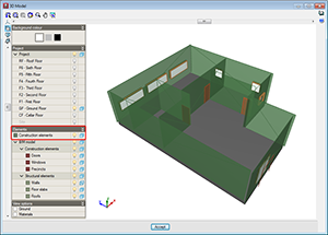
Construction elements are shown in a specific layer in the 3D view, which helps users to distinguish the non-structural walls that are present in the architectonic model and have been taken into account in the analysis of the structure.
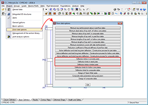
Deflection limits of joists depending on their material
The option: “Deflection limits in joists” has been divided into three to establish different deflection limits for concrete, steel and timber joists.
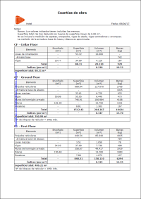
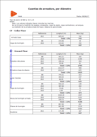
Take-off report
The “Job take-off report” has been improved and a new type of report: “Reinforcement quantities, per diameter” has been added.
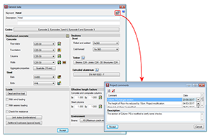
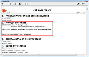
Project comments
A tool has been implemented which allows users to add a history of comments to a project. These comments are added and managed in the “General data” dialogue box. All these comments can be displayed in the “Job data” report. This improvement allows users to manage a useful history of comments, changes, modifications or revisions carried out on the project.
CYPE 3D
Earthquake-resistant systems in accordance with ANSI/AISC 341-10
As of the 2018.a version, CYPE 3D allows for the main specifications and requirements linked to the three most common seismic resistant systems defined in the American AISC 341-10 code (Seismic Provisions for Structural Steel Buildings) to be included in the design of welded and rolled steel structural elements:
Also implemented is the analysis, design and check of Prequalified Connections in accordance with the ANSI/AISC 358-10 and ANSI/AISC 341-10 codes. The design and check of Prequalified Connections are exposed in detail in the section on “Prequalified connections in accordance with ANSI/AISC 358-10 and ANSI/AISC 341-10” of this webpage. These connections are applied to earthquake-resistant systems composed of “Moment-resisting frames”.
The following sections describe the three earthquake-resistant systems that are contemplated and the types into which they are sub-divided. The checks carried out by CYPE 3D for each type of system are described in the “Checks carried out” section of the “CYPE 3D, Earthquake-resistant systems in accordance with ANSI/AISC 341-10, and prequalified connections in accordance with ANSI/AISC 358-10 and ANSI/AISC 341-10” webpage, which will be available shortly.
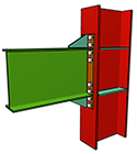
Moment-resisting frames
Unbraced frames or moment-resisting frames are an assembly of straight beams and columns connected to one another with welds, bolts or both. The bars making up these frames are mainly exposed to bending moments and shear forces, which control their design.
The specifications of AISC 341-10 consider three types of moment-resisting frames in accordance with the grade of ductile behaviour considered in the design. The fundamental difference between them is that they are designed with different energy dissipation levels:
- OMF – Ordinary Moment Frames (AISC 341-10, E1)
- IMF – Intermediate Moment Frames (AISC 341-10, E2)
- SMF – Special Moment Frames (AISC 341 -10, E3)
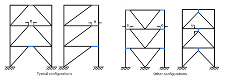
Frames with concentric bracing
This type of structure is characterised because the central axes of the component structural members are cut at a point, forming a grid-like structure. This is why lateral actions mainly induce axial forces in the bars of the braced frame.
The specifications of AISC 341-10 consider two categories for concentrically braced frames depending on the expected performance level:
- OCBF – Ordinary Concentrically Braced Frames (AISC 341-10, F1)
- SCBF – Special Concentrically Braced Frames (AISC 341-10, F2)

Frames with eccentric bracing
In eccentrically braced frames, axial forces induced in the braces are transferred via shear forces and moments in segments of a reduced length (e), called links, where energy, due to creep of the steel, is dissipated. The links represent “structural fuses”, which should be detailed adequately to avoid local buckling and other instability phenomena from degrading the response.
The specifications of AISC 341-10 consider a single category of frames with eccentric bracing:
- Eccentrically braced frames – EBF (AISC 341-10, F3)
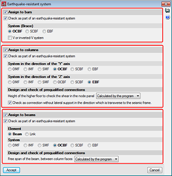
Assignment of earthquake-resistant systems in CYPE 3D
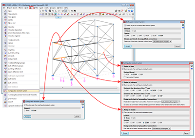
Users can assign earthquake-resistant properties to a bar using the “Earthquake-resistant system” option of the “Bar” menu. This option is only available if the selected rolled steel code is “ANSI/AISC 360-10”.
Users can freely assign the earthquake-resistant properties to bars and in accordance with their own criteria. Logically, it should be coherent with the geometry of the frame.
Bars that have been assigned earthquake-resistant systems must be rolled or welded steel bars and be defined as Generic bars, Columns or Beams.
- Generic structural elements (bracing)
Generic-type bars are those which are going to be used as bracing, and so, it is only possible to assign OCBF, SCBF or EBF systems to them. - Column-type structural elements
Any of the indicated earthquake-resistant systems (OMF, IMF, SMF, OCBF, SCBF or EBF) can be assigned to Column-type bars in the direction of the local “Y” and “Z” axes. The earthquake-resistant system can be different in either direction.
When checking prequalified connections and if the selected earthquake-resistant system is IMF or SMF, it is possible to indicate if the “Height of the higher floor to check the shear in the node panel” is calculated by the program or if it is indicated by users. It is also possible to activate the option: “Check as connection without lateral support in the direction of the seismic frame”, which is applicable to connections of SMF-type frames. More information on these two options can be found in the sub-section: “Operation in CYPE 3D” (including the section: “Prequalified connections in accordance with ANSI/AISC 358-10 and ANSI/AISC 341-10”). - Beam-type structural elements
Beam-type bars can be assigned any of the indicated earthquake-resistant systems (OMF, IMF, SMF, OCBF, SCBF or EBF) if the “Beam” option is selected as the “Element”. If users select the “Link” option as the “Element”, no type of system will be available to be assigned, because “Links” correspond to EBF earthquake-resistant systems, which is the type that is assigned automatically.
When checking prequalified connections, if the “Beam” option is selected as the “Element”, users can mark if the “Free span of the beam, between column faces” is to be calculated by the program or defined by users. More information on these two options can be found in the sub-section: “Operation in CYPE 3D” (including the section: “Prequalified connections in accordance with ANSI/AISC 358-10 and ANSI/AISC 341-10”).
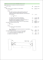
Prequalified connections in accordance with ANSI/AISC 358-10 and ANSI/AISC 341-10
As of the 2018.a version, CYPE 3D includes the analysis, design and check of prequalified connections in accordance with ANSI/AISC 358-10 (Prequalified Connections for Special and Intermediate Steel Moment Frames for Seismic Applications) and ANSI/AISC 341-10 (Seismic Provisions for Structural Steel Buildings).
Prequalified connections are applied to Special Moment Frames (SMF) and Intermediate Moment Frames (IMF) as indicated in the ANSI/AISC 341-10 code.
It is possible to define prequalified connections in projects in which the rolled and welded steel code: ANSI/AISC 360-10, has been selected.
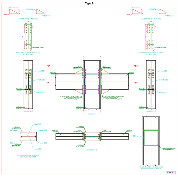
Implemented prequalified connections
The prequalified connections that have been implemented in the program are:
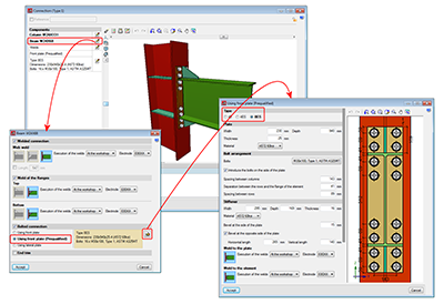
- 4E four-bolt unstiffened
- 4ES four-bolt stiffened
- 8ES eight-bolt stiffened
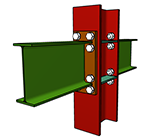
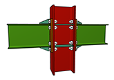
Nodes with interaction of several beams
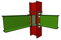
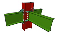
Column-beam prequalified connections can be part of a node interacting with connections of other beams, which can or cannot be prequalified connections. For example:
- Prequalified 4E connection to the flange of the column and moment connection to the web of the column and ordinary front plate.
- Prequalified 8E connections to the flanges of the column and pilled connection using lateral plate to the web of the column.
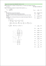
Checks and drawings
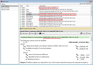
As well as the checks carried out on the connection in accordance with the ANSI/AISC 360-10 rolled steel code, specific checks of the ANSI/AISC 341-10 and ANSI/AISC 358-10 codes are carried out. The check report displays the chapter of the code in accordance which the check is performed.
Operation in CYPE 3D
For CYPE 3D to carry out the analysis, design and check of prequalified connections of columns and beams, the following conditions must be met:
- The rolled steel code must be ANSI/AISC 360-10
- The bars reaching the node must be column-type and beam-type
- The earthquake-resistant system assigned to the bars reaching the node must be that of Special Moment Frames (SMF) or Intermediate Moment Frames (IMF).
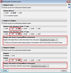
When the type of earthquake-resistant system is assigned to columns and beams, it is also possible to:
- Define the height of the higher floor to check the shear in the node panel
This parameter can be calculated by the program or established by users. It is used to calculate the shear of the column above that would affect the check of the shear in the node panel. - Check as connection without lateral support in the direction of the seismic frame
Users can choose whether or not to carry out this option depending on the bracing there may be in the elements of the connection. This check is only carried out for SMF frames. - Free span of the beam, between column faces
Value required to calculate the moment at the face of the column, this value can be calculated by the program or provided by users.
CYPE-Connect
Prequalified connections in accordance with ANSI/AISC 358-10 and ANSI/AISC 341-10
As occurs in CYPE 3D, as of the 2018.a version, CYPE-Connect includes the analysis, design and check of prequalified connections in accordance with ANSI/AISC 358-10 (Prequalified Connections for Special and Intermediate Steel Moment Frames for Seismic Applications) and ANSI/AISC 341-10 (Seismic Provisions for Structural Steel Buildings).
Prequalified connections are applied to Special Moment Frames (SMF) and Intermediate Moment Frames (IMF) as indicated in the ANSI/AISC 341-10 code.
It is possible to define prequalified connections in projects in which the rolled and welded steel code: ANSI/AISC 360-10, has been selected.
For more information on which prequalified connections have been implemented, how beams interact at the same node, the checks that are carried out and drawing that are generated, please consult the relevant sections in the new features of CYPE 3D of this webpage.
Operation in CYPE-Connect
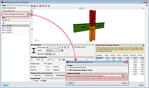
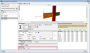
To calculate prequalified connections in CYPE-Connect, users must select the rolled steel code: ANSI/AISC 360-10, the connection in question must have the geometry corresponding to one of the implemented prequalified connection types, and the moment earthquake-resistant system option in the “Edit the geometry of the node” dialogue box must be activated with one of the available systems (SMF – Special Moment Frame, or IMF – Intermediate Moment Frame).
Even though no checks are carried out on cold-formed steel for prequalified connections, for internal operation purposes of the program, the selected cold-formed steel must be one CYPE-Connect considers to be compatible with the ANSI/AISC 360-10 code, such as “AISI S100-2007”.
As well as the earthquake-resistant code that is used, the following parameters must be defined:
- The height of the higher floor
It is defined in the dialogue box where the earthquake-resistant system is selected and is required to estimate the shear of the column and check the shear in the node panel. - Check as connection without lateral support in the direction which is transverse to the seismic frame
To check the requirements of article “E3.4c” of the “ANSI/AISC 341-10” code, this option must be marked, which is also available in the dialogue where the earthquake-resistant system is selected. - Free span of the bar
It is used to establish the moment at the face of the column. It is introduced in the “Edit node geometry” dialogue box (“Check” section).
AcoubatBIM by CYPE
Edit the ProductID in the personalised elements of the database
As of the 2018.a version, AcoubatBIM by CYPE allows for the ProductID of the elements of the database of Acoubat that have been generated by users to be modified. Thanks to this implementation, compatibility issues are avoided when sharing projects containing personalised products with other users.
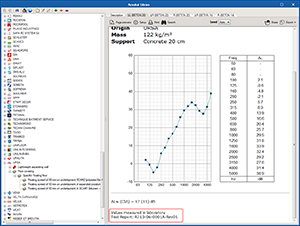
Reference of acoustic measurements
The source of the acoustic data has been included in the files corresponding to the products of the Acoubat database. If they have been obtained from laboratory measurements, the reference of the test is also displayed. Furthermore, users can also indicate the origin of the data that has been introduced for the element.
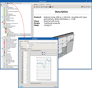
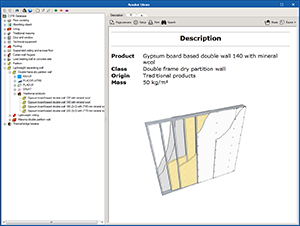
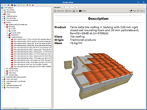
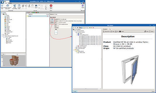
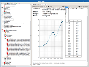
Description of the database products
The “Description” tab has been added in the panel of the products contained in the database of acoustic tests of Acoubat. Within this tab, the general definition of the product can be viewed and, for cases for which it is available, a representative image of the element.
Links to manufacturer websites
A new option has been introduced in the access panel of the Acoubat database that directs users to the website of the manufacturer of the selected element. This way, a direct connection is established between the products offered by manufacturers and the acoustic analysis software.
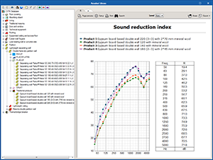
Comparison of database products
A new tool has been added that allows users to compare the acoustic data of several products of the database. It is possible to select up to 4 different elements whose corresponding acoustic index value graphs of values are displayed simultaneously. This way, users can easily compare the behaviour of products of different manufacturers and/or behaviour.
Calculation of airborne noise transmitted by air inlets
A new air inlet library has been introduced in the program where the acoustic properties of these elements can be defined. Once the different types have been defined, they can be included in walls and floor slabs of the model as is done with doors and windows.
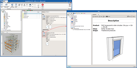
Calculation of airborne noise transmitted by roller shutter boxes
A new option has been introduced in the window types of the library, which allows users to indicate if there is a roller shutter box and its acoustic properties based on the products that are available in the Acoubat database. Users must specify the length of the shutter box for each window in the project. This value will be filled in automatically if a geometric BIM model has been imported that contains this information.
List of products used in the project
As of the 2018.a version, AcoubatBIM by CYPE automatically generates a document indicating the products used in the project and their acoustic properties based on the information contained in Acoubat’s library.
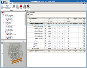
Improvement in the aspect of results
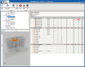
More information has been introduced in the global results list of each space. Now, it is possible to differentiate vertical, horizontal and diagonal orientations for each emitter-receptor couple for indoor airborne noise and impact noise calculations. New icons have also been included for each type of opening, this way, in the version, it is possible to distinguish between windows, skylights, doors, air inlets and roller shutter boxes. Finally, the references of each element have been modified so they correspond with those used in the results list.
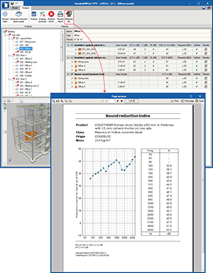
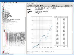
Adjustment of graph scales
Now, AcoubatBIM by CYPE allows users to modify the scale of the acoustic indices of the graphs of the program. Users can choose if the values are to be displayed depending on the maximum or minimum level of the curve. It is also possible to establish a specific maximum value or allow the program to establish it automatically.
Grouping of façades
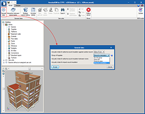
A new option has been added in the general parameters of AcoubatBIM by CYPE where users can configure the way insulation against outdoor airborne noise is to be verified. As well as the individual analysis of each façade that has been carried out up to now, it is now possible to combine all the external façades and check the insulation of the complete envelope of each space. The program also allows users to group adjacent walls that share the same orientation and determine the insulation of these combined elements. Lastly, the enclosures can be grouped depending on their type (façade, roof or overhang) and calculate each separator group.
CYPEFIRE Sprinklers
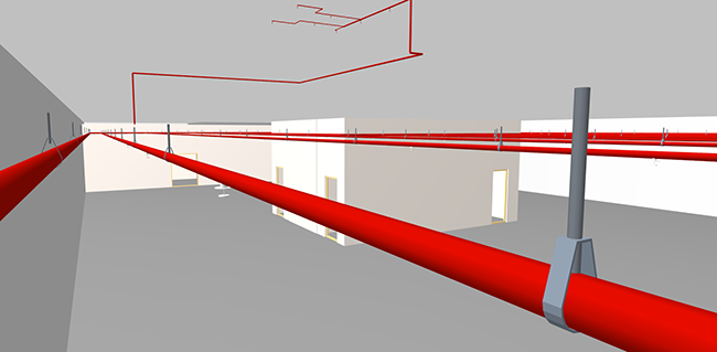
Supports for sprinkler systems
In the 2018.a version, it is possible to install supports to hold the load of the sprinkler systems. The quick and effective introduction of this type of supports, which is required for any type of installation, allows users to carry out the necessary checks to ensure that installation is done correctly, to obtain the justification of the individual checks of each support, detailed plans of the installation and material quantities, as well as the export to FIEBDC-3 to obtain the bill of quantities.
The introduction of the supports can be carried out by loading the catalogue offered by default by CYPEFIRE Sprinklers or by generating the user’s own catalogue of supports.
If users opt to generate their own catalogue, a standard series of data has to be specified, to define the “pear-type” support:
- Nominal diameter of the pipe to support
- Diameter of the threaded rod of the support
- Geometric data of the support
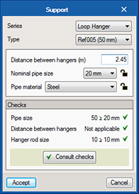
Once the catalogue of supports has been defined, they are easily introduced. First the diameter of the pipe to support is defined, as is the material of the pipe and the distance between the supports that are going to be introduced. Then, all that must be done is to place them over the pipes and look through the individual checks of each support to ensure no errors exist.
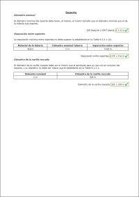
With the data that has been introduced, CYPEFIRE Sprinklers will perform checks on all the supports and display a report with the following checks:
- Maximum distance between hangers
Depending on the nominal diameter and the material of the pipe, this separation could vary. - Diameter of the hanger rod
Depending on the diameter of the pipe to be supported, the diameter of the threaded rod will vary. - Nominal diameters
The program will ensure that the assembly being used is correct, avoiding large diameter pipes to be held by small supports.
CYPETHERM HE Plus, CYPETHERM RECS and CYPETHERM EPlus
Open BIM workflow. Import TOSHIBA VRF equipment systems from IFC files
The TOSHIBA VRF air conditioning equipment defined in CYPETHERM HVAC can be imported directly in CYPETHERM programs with the EnergyPlusTM engine (CYPETHERM HE Plus, CYPETHERM RECS Plus and CYPETHERM EPlus) with the Open BIM connection using the IFC standard.
This way, in CYPETHERM HE Plus, CYPETHERM RECS Plus and CYPETHERM EPlus, it is possible to directly simulate the energy consumption of VRF installations designed in CYPETHERM HVAC without having to reintroduce them, if the project that has been created in these programs is linked to an Open BIM project.
Several VRF terminal units per thermal zone
As of the 2018.a, CYPETHERM programs with the EnergyPlusTM analysis motor allow users to define several VRF type (indoor) terminal units associated to the same thermal zone. In previous versions it was only possible to simulate one VRF terminal unit in each thermal zone.
Radiant heating and other types of terminal units in the same thermal zone
Within the air conditioning systems, it is possible to simulate a radiant heating terminal in a thermal zone that contains any other type of terminal unit (except the constant performance equipment).
Until now, a radiant heating terminal situated in a thermal zone in which another terminal unit was present was defined in the panel of the latter element. As of the 2018.a version, the radiant heating terminal must always be defined as an independent terminal unit associated to the corresponding thermal zone.
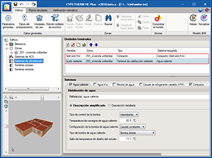
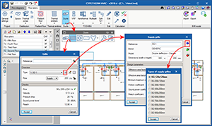
CYPETHERM HVAC
TOSHIBA Multi-Split Systems
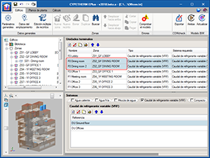
As of the 2018.a version, it is possible to define TOSHIBA multi-split systems. These systems consist of an outdoor unit and between 2 and 5 indoor units.
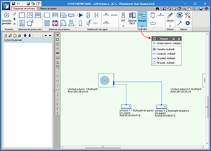
The design process is as follows: users place the indoor units (cassette, duct, wall or floor units) in the spaces, and the outdoor unit on the façade or roof of the building. They are joined using refrigerant pipes in the Flow diagrams tab.
Upon designing, the program automatically selects the indoor and outdoor models, as well as the diameter of the pipes. Regarding the results, the program generates, as well as the drawings, a design report of the system and the quantities of the elements provided in the installation.
Between 2 and 5 indoor units can be connected to the outdoor units that have been provided.
For CYPETHERM HVAC to be able to design a TOSHIBA Multi-split system, the user license must contain the “Direct expansion systems” permission.
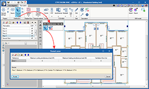
Thermal zones
The concept “thermal zone” has been introduced. A thermal zone is a group of spaces with a simultaneous thermal zone, which is used to define the power required in the production equipment.
Thermal zones could already be defined in CYPETHERM LOADS. As of the 2018.a version CYPETHERM HVAC can import them and assign them the load required in an Aerothermal system.
Grilles library
A library of discharge, return and extraction grilles with generic values has been added.
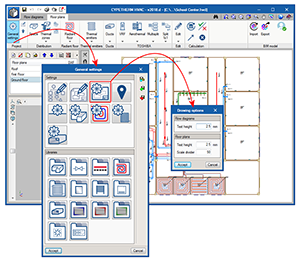
Text sizes in diagrams and drawings
The icon “Drawing options” has been implemented in the “General settings” dialogue box, using which a panel can be accessed in which the height of the texts of the Circuit diagram and Floor plans can be defined. These values will affect the texts of the diagram and drawing on-screen and when they are printed or exported to files of the available formats. The standard sizes in accordance with ISO 3098-0:1997 Technical Product Documentation are the following: 1.8 mm, 2.5 mm, 3.5 mm, 5.0 mm, 7.0 mm, 10.0 mm, 14.0 mm, 20.0 mm.
For Floor plans, the height of the text and scale of the drawing is defined. The scale of the drawing will not affect the height of the text that has been defined.
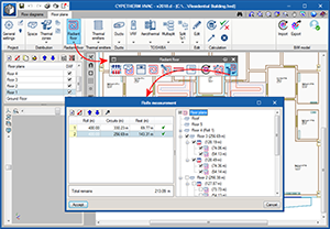
Quantities of radiant floor pipe rolls
In the 2018.a version, CYPETHERM HVAC incorporates a new tool to generate and manage the quantities of the radiant floor pipe rolls and their sub-division in circuits.
Users can accept that proposed by the program, modify it or create their own distribution from the beginning. To do so, the tool incorporates an automatic generation assistant and the tools required to create or modify the distribution of the rolls. It also manages the circuits so that no quantities are duplicated due to manual modification. It displays the length of each circuit at all times and the length remaining in each roll.
The quantities generated by this tool are included in the results report as well as in the quantities report.
Arquimedes
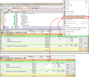
Unlink the “Formula” column in quantity subtables
The option to unlink the “Formula” column from a quantities subtable has been implemented.
The option “Unlink this column from the reference” is added and appears upon pressing the right mouse button on the reference of the subtable corresponding to the Formula column. If the column is already unlinked, the option changes to “Re-link this column to the reference” upon pressing the right mouse button in the same position, which allows users to recreate the link that was previously eliminated.
Key notes with identification of the job item with its parent chapter
If the Key note parameter has been used in a Revit model to reference several job items to the same Type, and the same job item is used in different chapters of the bill of quantities of Arquimedes, the following code must be introduced: chapter_code/job item_code to identify each repeated job item with its respective chapter.
The symbol used to separate the Chapter and Job item can be one of the following: “/”, “\” or “|”. For multiple job items, the symbol can be one of the following: “,” , “;” or “:”.
Return to the 2018 version download area
Tel. USA (+1) 202 569 8902 // UK (+44) 20 3608 1448 // Spain (+34) 965 922 550 - Fax (+34) 965 124 950