
- New modules
- Code implementation and improvements in its application
- CYPECAD
- CYPE 3D
- Design and check of reinforced concrete columns, and composite steel and concrete column check
- Job menu. General data
- Job menu. Dimensioning units
- New job assistant
- Tools menu (new)
- Planes menu
- Window menu. Plan views and elevation views
- Bar menu. Introduction of bars as structural elements
- Properties of Column-type structural elements
- Properties of Beam-type structural elements
- Analyse menu
- Drawing selection
- User license
- Design and check of reinforced concrete columns, and composite steel and concrete column check
- CYPE 3D and CYPE-Connect
- CYPECAD MEP
- Arquimedes
- Return to the 2016 version download area
New modules
Composite steel and concrete columns (Structures)
Using the “Composite steel and concrete columns” module, CYPECAD and CYPE 3D can check composite steel and concrete columns in accordance with the “EN 1994-1-1” and “ANSI/AISC 360-10” codes.
The code to be used for the composite column check is not selected directly as is done with the concrete and steel codes. The program applies a code depending on the selected concrete code.
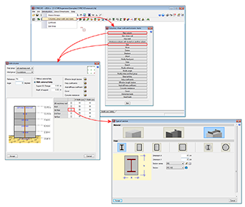
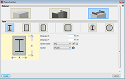
Below are the implemented types of composite columns:
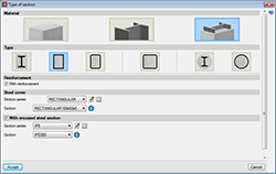
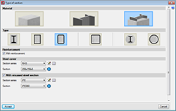
- Rectangular section with encased section
Always includes longitudinal and transverse reinforcement
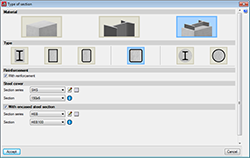
- Rolled steel plate box section, filled with concrete
It is possible to include longitudinal and transverse reinforcement, and an encased steel section.
- Cold-formed rectangular hollow section, filled with concrete
It is possible to include longitudinal and transverse reinforcement, and an encased steel section.
- Cold-formed square hollow section, filled with concrete
It is possible to include longitudinal and transverse reinforcement, and an encased steel section.
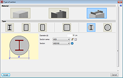
- Circular column with encased section
Always includes longitudinal and transverse reinforcement.
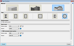
- Cold-formed circular hollow section, filled with concrete
It is possible to include longitudinal and transverse reinforcement, and an encased steel section.
More information on this new CYPECAD and CYPE 3D module can be found on the Composite steel and concrete columns webpage. 
Code implementation and improvements in its application
Concrete code
ACI 318M-11 (USA)
Building Code Requirements for Structural Concrete (ACI 318M-11)
Implemented in CYPECAD, CYPE 3D and Continuous beams.
CYPECAD and CYPE 3D use the Advanced beam editor and Advanced column editor when applying this code.
CYPECAD
Composite steel and concrete columns
As of the 2016.a version, CYPECAD and CYPE 3D can check composite steel and concrete columns. This check is included in the “Composite steel and concrete columns” module described in the “New modules – Composite steel and concrete” columns section on this webpage.
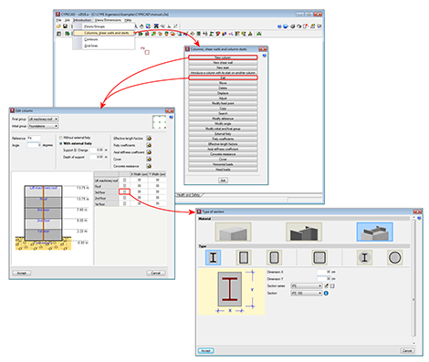
New column editing features
The 2016.a version brings about changes and new features to the Advanced column editor.
Furthermore, since, as of this version, users can design concrete columns and beams, as well as check composite steel and concrete columns, the advanced editor is now a tool used in CYPECAD and CYPE 3D.
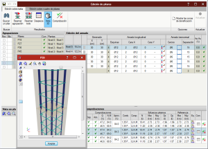
The new version of the column editor contains two tabs which appear on the top part of the screen, with which, users can carry out the required checks and modifications on two different views: the classic view available as of previous versions “Edit in table” tab and the column schedule “Edit in column schedule” tab.
Edit in table
This window allows users to edit a column in a table (top right section of the window) which displays all the spans of the selected column. A summary of the checks carried out on the column span selected in the previous table is also displayed (in the bottom right section of the window).
It is also very useful to show the ultimate limit state (U.L.S.) checks of the selected column span or all the spans of the column.
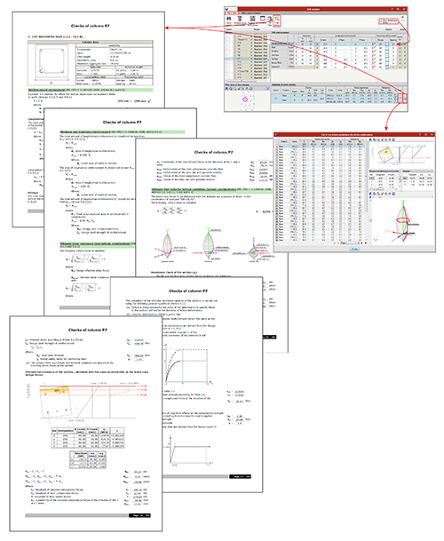
Some buttons are displayed in the top right section, which allow users to: search for a column, redesign the reinforcement of a group of columns, view the details of the selected column, see its 3D view and obtain the U.L.S. check report of all the spans of the selected column.
Included in the top right section of the editor is the “Show densification zones”, which shows or hides, in the edit reinforcement window (top right section), the stirrup spans a concrete or composite column may have. This option only displays the stirrup densification zones each column span may contain but does not allow users to add any other densification zones. This is only possible in the Edit in column schedule window.
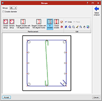
When stirrups are edited (by clicking on the stirrup layout in the table), a dialogue box opens where users can add different types of stirrups and crossties to a column span, hence the stirrups of the column can be modified even though their arrangement is not included in the reinforcement tables. This editing option is also available in the Edit in column schedule window.
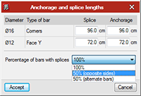
Users can also edit the longitudinal reinforcement splices of each span and indicate that the splice length of 50% of the bars (of opposite sides or alternate bars) is to be displaced by a specific distance. To do so, select the icon in the cell located to the right of the “Y face” longitudinal reinforcement. Splices can also be edited and displaced in the Edit in column schedule tab by selecting the “Splices and anchorages” button of the longitudinal reinforcement.
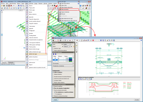
Edit in column schedule
This window has been especially designed to edit the reinforcement and steel sections provided in each span of the column groups, and in this case in the view of the column schedule that will be obtained in the drawing.
It contains more editing tools than the “Edit in table” window. Along the top of this window are buttons with which users can:
- Column search
- Filters
This option is very useful when the job contains many column and/or floor groups, since it allows users to select the floors and groups to be displayed. - Groups
The following operations can be carried out in the column schedule, in the schedule itself:- Join groups
- Divide groups
- Modify groups (to another group)
- Match groups
- Match data (without grouping columns)
- Reorganise groups
- Edit geometry
- Longitudinal reinforcement (for concrete columns and composite columns)
- Edit
- Insert
- Splices and anchorages

- Delete
- Transverse reinforcement (for concrete columns and composite columns)
- Edit
- Insert
- Densification zones
Allows users to modify, add or delete stirrup spacings in a column span. - Delete
- Edit
- Results
- Redesign group reinforcement
- Redesign all reinforcement
- Code check
- Detailing
- 3D view
Detailed information on this powerful CYPECAD and CYPE 3D tool can be found on the “Advanced column editor” webpage.
Jobs analysed with previous program versions
To avoid problems arising with jobs analysed with versions earlier than the 2016.a version, the new column editor features do not appear until the job has been reanalysed with the new version. If there are any blocked columns, the new features will continue to not appear even if the job has been reanalysed. Therefore, all columns must be unblocked and the job reanalysed to be able to edit columns with the new editor.
Base shear condition verification. Results adjustment
Some seismic codes have a minimum base shear requirement when applying the modal spectral dynamic method in the seismic design process. CYPECAD carries out this check as of previous versions. More information on this check as well as the implemented codes for which this check is carried out can be found in the “Correction due to base shear” section on the CYPECAD webpage.
When the total results of the dynamic analysis are less than the minimum values prescribed in the seismic code to be applied, the dynamic response parameters have to be adjusted by increasing them using a modification factor, until these minimum values are reached. When the response exceeds the prescribed code values, the parameters of the total dynamic response can be reduced proportionally according to the project designer’s criteria.
Therefore, in the 2016.a version, the program offers different ways of proceeding with this requirement. The modification factor to adjust the results can be defined in different ways:
- Do not carry out the static base shear correction
This option allows users to not apply the base shear check and, therefore, not adjust the results, based on the project designer’s criteria. - Based on the code
This was the only option CYPECAD had to offer in previous versions. Using this option, the program adjusted the results by calculating the modification factor in accordance with what was specified in the corresponding seismic code. The design code specifies that the base shear resulting from the dynamic analysis be greater than a specific percentage of the static shear defined in the code. This percentage depends on how ‘regular’ the structure is. - Specify the static base shear percentage
Using this option, users can define, in accordance with a justified criteria, what static base shear percentage is to be taken as the minimum limit to be reached n the dynamic results. - Specify the modification factors
It is recommended this option be used after an initial analysis has been run and its results analysed. By comparing the dynamic and static shear values, a second analysis can be launched with the modification factor values users consider to be adequate. A factor can be defined for each loadcase and analysis direction. This last option also allows for the maximum base shear condition, contemplated in some seismic codes, to be applied. The modification factor can have a value smaller than one, so that the dynamic results are reduced when these exceed the maximum limit established in the design code.
Axial stiffness coefficient, Cover and Concrete resistance when introducing and editing a column
Users could, as of previous versions, edit and modify the axial stiffness coefficient and the concrete cover and resistance of an existing column using the corresponding options in the “Columns, shear walls and starts” dialogue box (“Introduction” menu in the “Column Definition” tab). Now, these options appear in the “New Column” dialogue box and in the “Edit Column” dialogue box (Column Definition tab > Introduction > Columns, shear walls and starts > “New Column” or “Edit”). This way, these parameters can be edited more comfortably, especial when they all have to be edited. These options can be found with the edit buckling and fixity coefficients options, which were already present in earlier program versions.
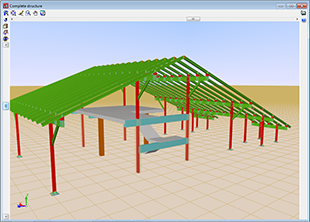
V-bracing
In previous versions, users could introduce diagonal cross bracing in their structures. As of the 2016.a version, a new option has been implemented to generate V-bracing. “Add V-bracing” and can be found in the “Sloped beams” menu (Beams/Walls > Sloped beams).
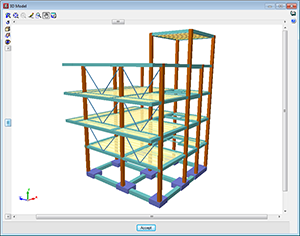
CYPE 3D
Design and check of reinforced concrete columns, and composite steel and concrete column check
As of the 2016.a version, CYPE 3D analyses, designs and checks reinforced concrete beams and columns; and checks composite steel and concrete columns. It also provides reinforcement and U.L.S. check reports for columns, reinforcement and U.L.S. and S.L.S. check reports for beams, the column schedule and column details drawings and beam details drawings.
All the options that have been mentioned in relation with reinforced concrete columns and composite columns are available for the design codes implemented in the Advanced column editor and those in relation with reinforced concrete beams are available for the design codes implemented in the Advanced beam editor.
Columns and beams are defined as being structural element types in the CYPE 3D model when they are introduced. As of the 2016.a version, CYPE 3D allows users to define 4 types of structural elements: Generic, Tie, Column and Beam.
For the program to process an element as a column or beam, it must be introduced as a column or beam or have been assigned the corresponding structural type beforehand.
Reinforced concrete columns and beams are used mainly in building structures. Building structures are fundamentally vertical, divided into floors and composed of frames. As of this version, CYPE 3D incorporates levels and grids. Levels allow for space to be divided by horizontal planes at different heights, which allows for work zones, equivalent to floors, to be defined, and so allowing work with beam-type elements to be carried out more easily. Grids allow for numbered elevations to be defined in the x and y directions, allowing for columns to be defined more easily.
To help users when working with these structures, CYPE 3D allows users to define level and elevations views, in which users can move between the levels and elevations they have defined. Users are not obliged to define the grid (although it is very useful when moving between elevations, users must however, define at least two levels to be able to introduce column-type elements.
Due to the introduction of these elements, the program interface has been reorganised and some operations have been redefined.
Job menu. General data
Two new options have been implemented in the Job menu: “General data” and “Dimensioning units”. Details of the “General data” dialogue box are provided in this section.
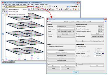
The “General data” option provides users with a central management dialogue box of all the options affecting the design and check parameters of the program (for both Structure and Foundations tabs).
Added to the existing options, which were previously located in other menus, are the following options:
- In the reinforced concrete section
- Cover
By clicking on this option, users can edit the cover of the reinforcement bars of beams and columns. - Aggregate properties
The nature and maximum size of the aggregates for columns, floor slab beams and foundation beams can be defined here. - Steel fabrication loss
Allows users to define the steel fabrication loss of columns and beams, as well as the fabrication loss for foundation elements.
- Cover
- Loads section
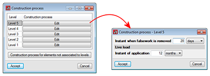
- Construction process
By using this option, users can edit the construction process for deflection checks of reinforced concrete beams. The editing process is carried out per level, and so only the beams located in each level are affected. The construction process of beams not located on a level can be defined by selecting the “Construction process for elements not associated to levels” button.
The editing process consists in defining the instant when the beam is unpropped, the instant when the dead loads are applied and the instant when the live loads are applied.
- Construction process
- Options section
- Columns
Options regarding the design and check of columns are found in this section. Reinforcement tables can be configured, as well as design and check options, reinforcement arrangement options and stiffness coefficients. - Beams
Options regarding the design and check of beams are included in this section:- Reinforcement and layout tables
- Error valuation
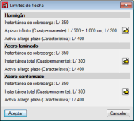
- Deflection limits
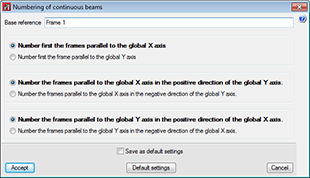
Users can configure the deflection limits depending on their material (concrete beams, rolled steel beams and cold-formed steel beams). - Numbering of continuous beams
The program numbers frames based on a base reference provided by users and the established configuration. - Numbering of beams
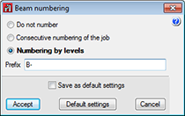
The program offers users the option whether or not to number beams. Beams are numbered based on a base reference provided by users and the established configuration.
- Environment section
The exposure class and specific exposure class for beams are defined here. The configuration defined in this section affects all beams, although users can, however, configure a specific environment for each beam in the Bar menu.
- Columns
Job menu. Dimensioning units
Allows users to establish the units in which the element dimensions are displayed in drawings.
New job assistant
The new job assistant present in previous versions has been substituted by the General data dialogue box, as it in this box where all the parameters affecting the analysis and design parameters of the program are located.
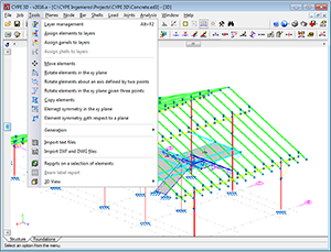
Tools menu (new)
Options related with layer management, generating, geometry management, 3D views and specific operations carried out on elements (which in previous versions were located in the “Job” menu), have been incorporated in this menu to improve the options structure of the program.
The option to print beam labels has also been implemented.
Planes menu
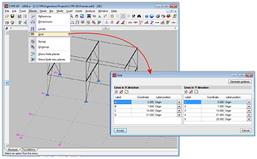
Two new options: Levels and Grids, have been incorporated in the “Planes” menu. These options are essential when introducing, revising and viewing jobs with “Column” and “Beam” type structural elements.
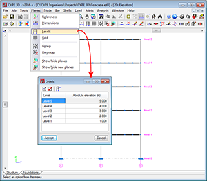
- Levels
Levels are horizontal planes parallel to the XY global plane, situated at a given global elevation where users can introduce a spatial sub-division as is the case in structural buildings. Assignment of the elements to the different levels is automatic. Elements situated between two levels are assigned to the closest lower level.
Levels are defined to support the introduction of structural elements as well as to define views of a level (which help when working on the elements of the structure). If columns are introduced, levels must be defined. Columns must begin and end at two different levels (although they may do so with there being an elevation change with respect to the two levels).
With this option, users can edit or delete levels. If the elevation of a level is modified, any elements contained in that level will be automatically displaced to the new position. - Grids
A grid is a mesh composed of lines parallel to the global x and y axes. These lines define a spatial division of the structure in its elevation. Users can assign a name to each gridline and control the position of the name. Gridlines are defined as support for the introduction of structural elements as well as for when defining elevation views (which help when working on the elements of the structure).
This option allows users to introduce, delete or edit Gridlines. A rectangular grid generator has been implemented. If the position of a gridline is modified, all the elements contained on the line will be automatically displaced to the new position.
By default, the grid will always be visible on-screen, unless it is deactivated using the option: “Planes > References”. The grid can also be displayed on drawings.
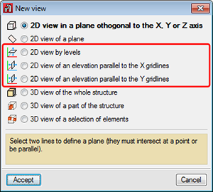
Window menu. Plan views and elevation views
If levels and grids have been defined, the program will allow users to create views for levels and elevations. Once the views have been defined, it is possible to move from one level to the next, or from one elevation to the next, using the 

 buttons (up, down, and select levels or elevations) of the scroll bar on the left of the main screen.
Both level views and elevation views are 2D views. Therefore, any element introduced in a view will be contained in that plane. In the case of level views, the program displays elements belonging to the level and those reaching or beginning from it. The program allows for the views to be rotated, so users can better adjust their view of the elements.
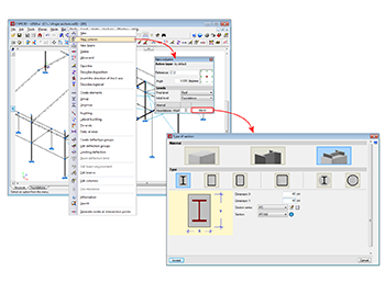
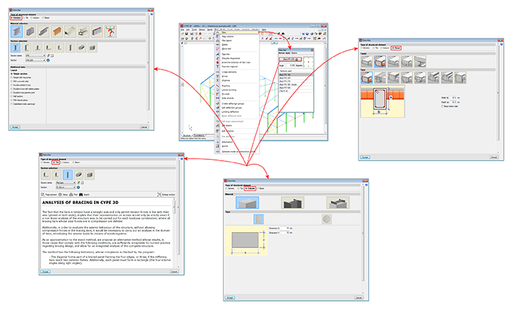
Bar menu. Introduction of bars as structural elements
As of the 2016.a version, users are required to define in CYPE 3D the structural function an element carries out. There are 4 different structural types available:
- Generic
The element does not have a structural role known by the program. It will be designed, edited and checked as were elements in previous program versions. - Tie
The element forms part of a bracing system and only works in tension. This type was already available in previous versions. - Column
The element is a column. It is designed, edited and checked using the Advanced column editor, and hence, it can only be designed in accordance with the codes that are available with the editor. Design codes which are no longer in force or in use are not usually available with the editor. The sections that can be assigned are:- Rectangular or square reinforced concrete sections
More information on this module, used by both CYPE 3D and CYPECAD and used to design these structural elements, can be found on the Concrete columns webpage. - Steel sections
Can be rolled steel, cold-formed steel or welded steel. - Composite steel and concrete sections
More information on this module, used by both CYPE 3D and CYPECAD and used to design these structural elements, can be found on the Composite steel and concrete columns webpage.
- Rectangular or square reinforced concrete sections
- Beam
The element is a beam. It is designed, edited and checked using the Advanced beam editor, and so it can only be designed in accordance with the design codes in the editor. The sections that can be assigned are:- Rectangular, L-section, T-section..., lattice or prestressed concrete beams
More information on this module, available for use with CYPE 3D and CYPECAD, can be found on the Concrete beams webpage. - Steel sections
Can be rolled steel, cold-formed steel or welded steel.
More information on these structural elements can be found in the section on Properties of Beam-type structural elements of this webpage. - Rectangular, L-section, T-section..., lattice or prestressed concrete beams

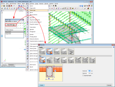
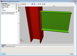
Properties of Column-type structural elements
Columns are composed of elements whose structural type has been defined as being a column. A column can be composed of one or more elements. The column elements making up the column are vertical and have the same level parameters. Columns can be created in 3 ways:
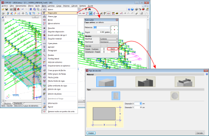
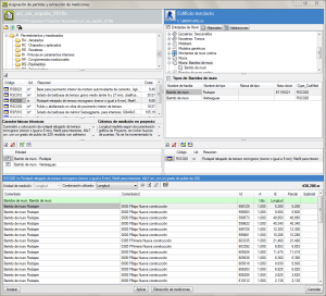
- By introducing a bar using the “New bar” option and selecting a column-type structural element description (Bar > New – see previous image).
- By assigning a column-type structural element to a previously introduced element (Bar > Describe).
- Using the “New column” option of the Bar menu.
Regardless of how they are created, the program will manage the composition/decomposition of the previously introduced columns. It is recommended columns be created using option 3. The “New column option” allows users to create a column between a range of indicated levels with the reference and sections defined by users by clicking with the mouse button at the position where the column is to be introduced.
The element must be vertical and be defined as being between two different levels. The element must be divided into bars, however, in the case of concrete columns, the reinforcement will be continuous along its complete length.
Once a group of elements has been defined as being a single column, CYPE 3D ensures the level parameters are the same for all of them. The level parameters of the column are defined using the “Describe disposition” option in the “Bar” menu.
The remaining specific editing option for columns are located in the “Edit columns” option in the “Bar” menu. This option displays a toolbar containing the possible edit options. These options are:
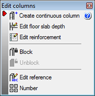
- Create continuous column
Creates a single column from a group of aligned elements - Edit floor slab depth
Allows users to edit the depth of the floor slab at a column node if they wish to assign a different value to that assigned automatically. The depth of the floor slab determines the free height of the column between levels. - Edit reinforcement
Allows users to edit column reinforcement by opening the column schedule. - Block
Blocks the reinforcement of a column so it is not modified during the design process. - Unblock
Unblocks any blocked reinforcement. - Edit reference
Edits the column references. - Number
Allows users to number consecutively all the columns of the job as of an initial reference.
The program generates a solid model of the column taking into account floor slab depths at the nodes of the elements it is composed of. CYPE 3D automatically analyses these floor slab depths based on the elements reaching the nodes to established the real size of the column as well as the free height of the spans it is composed of.
Properties of Beam-type structural elements
A beam is an element which has been assigned as being a beam-type structural element. A beam cannot be vertical, and the angle between its XZ plane and the vertical plane containing it must be zero (i.e. it must not rotate about the longitudinal axis of the beam). Beams can be grouped and so form continuous beams (beam alignments), with the following conditions:
- The end node of one is the starting node of the next.
- All are of the same type of material (concrete, rolled steel or cold-formed steel).
- If all are made of concrete, they must be of the same type of concrete.
Beams (and continuous beams) can be created in 3 ways:
- By introducing a bar using the “New bar” option then applying a beam-type structural element.
- By assigning beam-type structural element to a previously introduced element.
- Using the “New beam” option in the Bar menu.
In all these cases, the program will manage the composition/decomposition of beams that were introduced previously. The recommended option is option 3. The “New beam” option allows users to easily create a continuous beam by introducing the bars it consists of. To finish off the introduction, click on the right mouse button and at that moment, CYPE 3D will create a continuous beam with all the elements that have been introduced, if possible.
The element cannot be vertical, it does not have to belong to a level, however when they have been defined, they will be assigned to the closest level below the beam. The element can be divided into bars, but if it is a concrete beam, the reinforcement will be continuous along its complete length.
If the continuous beam is composed of more than one element, the deflection groups of the elements must be completely contained within the continuous beam. CYPE 3D will carry out the deflection analysis indicated by the design code for the beams of the continuous beam. No additional deflection limits have to be defined using the “Limiting deflection” option, even though in this case, the program will additionally carry out the check.
The remaining specific options for editing beams are found in the “Edit beams” option of the “Bar” menu. This option displays a toolbar containing options to edit beams. These are:
- Create continuous beam
Creates a new continuous beam by selecting the beams which wil become part of the new continuous beam. - Edit nodes
Edits the geometry of a continuous beam node if it is to be different to that which was established automatically. The geometry of the node affects the free span of the beams which is represented in the beam reinforcement editor, and therefore, the length of the reinforcement that is provided. - Edit adjacent floor slabs
Allows users to describe the floor slabs next to the bars making up the beams. With this option, the depth of flat beams can be defined and whether or not floor slabs are to be shown in the beam details drawing. Floor slabs are taken into account when checking the fire resistance of steel beams. - Edit reinforcement
Edits the beam reinforcement and opens the Advanced beam editor. - Assign reinforcement
Allows users to copy reinforcement from one beam to another. - Block reinforcement
Blocks the reinforcement of a beam to avoid if from being modified during the design process. - Unblock
Unblocks blocked reinforcement. - Edit beam or continuous beam references
Allows users to edit the beam references.
The beam reinforcement editing process implies that a solid model of the beam has been generated bearing in mind the size of the nodes of the elements making it up. CYPE 3D automatically obtains the geometry of these nodes based on the geometry and position of the elements not belonging to the beam. In any case if the analysis were not to be satisfactory, users can define their own node geometry.
Analysis menu
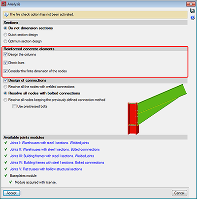
In the “Analysis” dialogue box (Analysis > Analyse), users can indicate whether reinforced concrete elements are to be designed. The section options affect steel columns and beams, even though in that case, the design process differs to that applied to bars defined as generic-type structural elements.
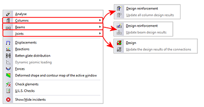
3 new options have been implemented in the “Analysis” menu (Columns, Beams and Joints), which open a series of design and analysis result update options:
- Design
Redesigns elements that have not been blocked. - Update design results
Once the elements have been edited, the results from the previous check may not be up to date (the program emits a warning if this is the case). Using this option, the results can be updated so the information displayed on-screen corresponds with the current definition status of the element.
The options corresponding to connections already existed in previous versions, but have been moved to this menu due to a better coherence of the options.
The “Check elements” and “U.L.S.” checks also include changes.
- Check elements
This option substitutes the old “Check bars” option. Now, users can use this option to check bars bearing in mind their structural-type.
For beams and columns, the corresponding editor is displayed to carry out the required changes. For any other type, a dialogue box appears displaying a list of all the sections of the series corresponding to the selected bar, indicating which sections meet all the checks and which do not. When the option is closed, if any changes have occurred, the structure will have to be re-analysed. Bars are displayed in different colours depending on whether or not they pass the checks. - ULS checks
Allows users to consult bar checks bearing in mind their structural type. When a bar defined as being a generic or tie-type structural element, the check panel is displayed bearing in mind their structural type. Bars are displayed in different colours depending on whether or not they pass the checks.
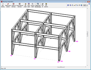
Drawing selection
With the new structural elements that have been introduced, CYPE 3D now generates the following drawings (File > Drawings):
- 3D structures
- Foundation floor plan drawing
- Foundation layout drawing
- 2D plane drawing
Drawing of a 2D view with steel connections. Users can include the references of the connections that have been applied and attach their details. - Joints
- Frames drawing (New)
- Detailing of columns (New)
- Column schedule (New)
User license
For CYPE 3D to design new structural elements (Columns and beams), the user license must include the following modules (as well as the required permits to use CYPE 3D):
- To design reinforced concrete columns
The user license must include the Concrete columns module. - To design composite steel and concrete columns
The user license must include the Composite steel and concrete columns module. - To design reinforced concrete beams
The user license must include the Concrete beams module. - To design steel columns or beams
If the column-type or beam-type structural elements are made of steel (rolled, cold-formed or welded steel), the program does not require any additional module to analyse them.
CYPE 3D and CYPE-Connect
Bolts
Thread dimensions and lengths have been updated for all bolt series. Bolt series A307 has been increased up to diameter 4.
Types of welds
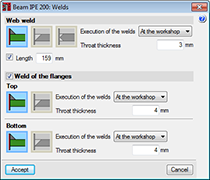
In versions earlier than the 2016.a version, the type of weld applied could not be edited. The welds are generally angle welds (except in connections with circular hollow sections and anchorage bolts).
As of the 2016.a version, the type of weld can be edited. Users can choose amongst:
- Fillet weld
- Full with complete penetration (simple bevel weld)
- Full with complete penetration (double bevel weld)
The welds will be represented on the plans with their corresponding symbols.
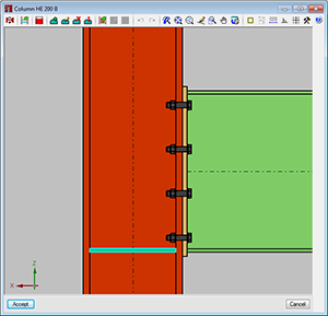
Connections without stiffeners
In previous versions, connections fixed to column or beam flanges, welded or bolted, required web stiffeners.
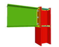
As of the 2016.a version, these connections can be defined without stiffeners. This option is available only to check the connection. If the connection is re-designed, stiffeners will be provided. Users has the option to delete the designed stiffeners and check the connection without the stiffened web. Stiffeners associated with a moment reinforcement in the connection to the web of the main section are required and cannot be eliminated.
CYPECAD MEP
Thermal analysis for France
The following update has been implemented in the “Thermique” tab of CYPECAD MEP for France:
- Update of the XML file of the RT 2012 code: Fiche Standardisée RT 2012, 7100_V1.2
Arquimedes
Automatic quantity measurement on drawings and link with CAD programs
Assign height for measurements with a vertical component
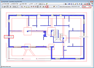
An option has been implemented to assign heights to measurements with a vertical component such as “Vertical surface area” measurements and “Volume of polygonal plan” measurements when using the “Automatic quantity import from drawings and link with CAD programs” module. To edit the height assigned to a vertical element click on the new “Assign height” button and in the “Height” box modify the value for the height. Then, select the “Vertical surface area” or “Volume of polygonal plan” measurement to change its height.
Bill of quantities of Revit models
Quantity combinations for job items measured by number of units
Quantity combinations for job items measured by number of units can now be created using the “Bill of quantities of Revit models” module.
Improvements in the change tracking system
The change tracking system has been improved for the “Bill of quantities of Revit models” module.
When the “Update changes carried out in Revit, in Arquimedes” option is used (after a change in the Revit model that is already linked to the Arquimedes job), a dialogue box appears: “Update the changed carried out in the Revit model linked to this job” where the entities of the Revit model are marked with  (entity not modified),
  (modified entity),
  (new entity) or
  (deleted entity).
By double clicking with the mouse button on a Revit entity (Type, Element, Material or Room) marked with the symbol, a dialogue box will appear displaying the parameters that have changed in red.
If users press the “Accept” button in the “Update changes carried out in the Revit model linked to this job” dialogue box, the changes will be saved and another dialogue box will appear: “Assign job items and quantity extraction” to continue with the work. However, if users cancel the “Update changes carried out in the Revit model linked to this job” dialogue box without accepting the changes, no dialogue box will be displayed.
Revit model sub-category import
As of the 2016.a version, sub-categories are included in the Revit model that is imported to Arquimedes. These appear at category level in the “Assign job items and quantity extraction” dialogue box in the “Revit entities” tab.
Quantity measurement by Sweeping
Since sub-categories can now be imported, length-type job items such as washboards, moulds, drains, etc, can be measured by sweeping.
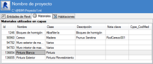
“Paint” material import
“Paint” has been added as a material to the Revit model. This way, quantities can be obtained using this Revit entity from the “Materials” tab of the “Assign job items and quantity extraction” dialogue box.
Return to the 2016 version download area
Tel. USA (+1) 202 569 8902 // UK (+44) 20 3608 1448 // Spain (+34) 965 922 550 - Fax (+34) 965 124 950